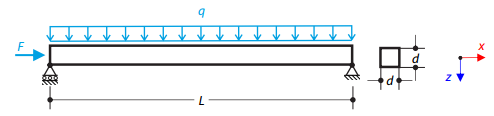
A steel beam with a square cross-section is loaded with an axial force and distributed loading. The image shows the calculation of the maximum bending deflection and critical load factor according to the second-order analysis.
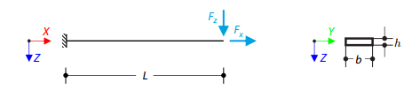
Prove that coupling different dimensional elements does not affect the results. A cantilever with a rectangular cross-section is fixed at one end and loaded at the other by concentrated forces. Neglecting its self-weight and assuming only small deformations, determine the cantilever's maximum deflections.
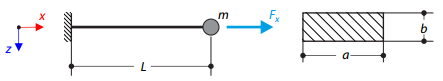
A cantilever of rectangular cross‑section has a mass at the end. Furthermore, it is loaded by an axial force. Calculate the natural frequency of the structure. Neglect the self‑weight of the cantilever and consider the influence of the axial force for the stiffness modification.
Verify that a beam of different cross-sections made of Alloy 6061-T6 is adequate for the required load, in accordance with the 2020 Aluminum Design Manual.
Determine the allowable axial compressive strength of a pinned 8-foot-long beam of various cross-sections made of Alloy 6061-T6 and laterally restrained to prevent buckling about its weak axis in accordance with the 2020 Aluminum Design Manual.
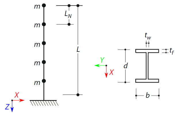
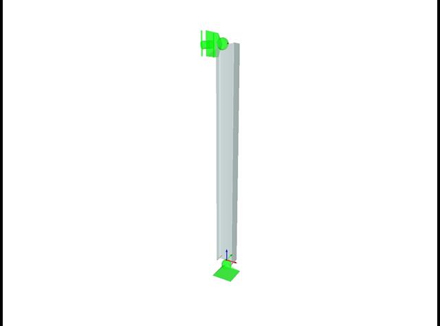
A cantilever beam with an I-beam cross-section of length L is defined. The beam has five mass points with masses m acting in the X-direction. The self-weight is neglected. The frequencies, mode shapes, and equivalent loads of this 5-DOF system are analytically calculated and compared with the results from RSTAB and RFEM.
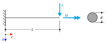
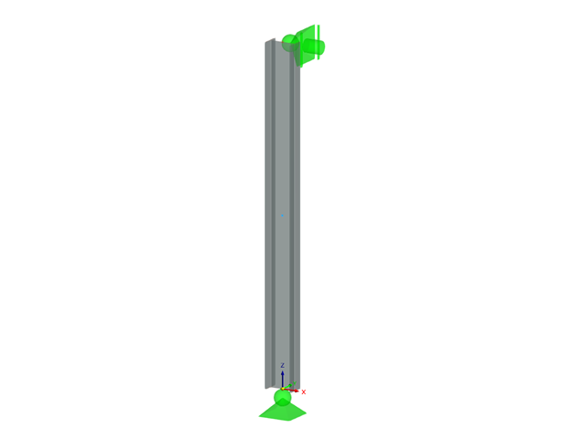
A cantilever with a circular cross‑section is loaded by a concentrated bending force and torque. The aim of this verification example is to compare the reduced stress according to the von Mises and Tresca theories.
Verify that a beam of different cross-sections made of Alloy 6061-T6 is adequate for the required load, in accordance with the 2015 Aluminum Design Manual.
Determine the allowable axial compressive strength of a pinned 8-foot-long beam of various cross-sections made of Alloy 6061-T6 and laterally restrained to prevent buckling about its weak axis in accordance with the 2020 Aluminum Design Manual.
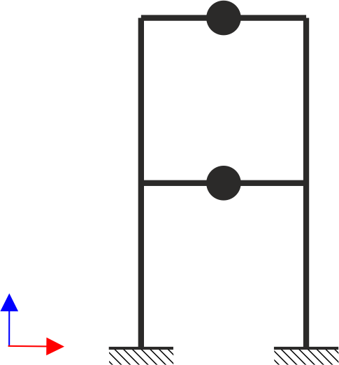
A two‑story, single‑bay frame structure is subjected to earthquake loading. The modulus of elasticity and cross‑section of the frame beams are much larger than those of the columns, so the beams can be considered rigid. The elastic response spectrum is given by the standard SIA 261/1:2003. Neglecting self-weight and assuming the lumped masses are at the floor levels, determine the natural frequencies of the structure. For each frequency obtained, specify the standardized displacements of the floors as well as equivalent forces generated using the elastic response spectrum according to the standard SIA 261/1.2003.